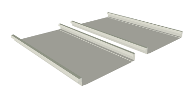
PC 216/218 Roof System

16″ Panel Features

-
Coverage Width16″
-
Rib Spacing16″
-
Rib Height2″
-
Min Slope1/2″ : 12″
-
Panel AttachmentStanding Seam
-
Gauge24 & 22
16″ Panel Specifications
| PANEL TOLERANCES | ||||||||
|---|---|---|---|---|---|---|---|---|
| PANEL GAUGE | DESIGN THICKNESS | ALLOWABLE SHEAR (Kips/ft) | ||||||
| 24 | 0.0221 | 0.79 | ||||||
| 22 | 0.0275 | 1.22 | ||||||
| Section Properties | ||||||||
|---|---|---|---|---|---|---|---|---|
| NEGATIVE BENDING | POSITIVE BENDING | |||||||
| PANEL GAUGE | Fy (KSI) |
WEIGHT (PSF) |
Ixx (IN.4/FT.) |
Sxx (IN.3/FT.) |
Ma (KIP-IN./FT.) |
Ixx (IN.4/FT.) |
Sxe (IN.3/FT.) |
Ma (KIP-IN./FT.) |
| 24 | 50 | 1.24 | 0.1943 | 0.1113 | 3.333 | 0.0900 | 0.0762 | 2.282 |
| 22 | 50 | 1.555 | 0.2490 | 0.1448 | 4.337 | 0.1155 | 0.1002 | 2.999 |
*Fy is 80-ksi material reduced to 60-ksi in accordance with the 2007 edition of the North American Specification for the Design of Cold-Formed Steel Structural Members – A2.3.2.
18″ Panel Features

-
Coverage Width18″
-
Rib Spacing18″
-
Rib Height2″
-
Min Slope1/2″ : 12″
-
Panel AttachmentStanding Seam
-
Gauge24 & 22
18″ Panel Specifications
| PANEL TOLERANCES | ||||||||
|---|---|---|---|---|---|---|---|---|
| PANEL GAUGE | DESIGN THICKNESS | ALLOWABLE SHEAR (Kips/ft) | ||||||
| 24 | 0.0221 | 0.70 | ||||||
| 22 | 0.0275 | 1.09 | ||||||
| Section Properties | ||||||||
|---|---|---|---|---|---|---|---|---|
| NEGATIVE BENDING | POSITIVE BENDING | |||||||
| PANEL GAUGE | Fy (KSI) |
WEIGHT (PSF) |
Ixx (IN.4/FT.) |
Sxx (IN.3/FT.) |
Ma (KIP-IN./FT.) |
Ixx (IN.4/FT.) |
Sxe (IN.3/FT.) |
Ma (KIP-IN./FT.) |
| 24 | 50 | 1.218 | 0.1760 | 0.0987 | 2.955 | 0.0800 | 0.0676 | 2.023 |
| 22 | 50 | 1.507 | 0.2253 | 0.1281 | 3.873 | 0.1027 | 0.0889 | 2.661 |
*Fy is 80-ksi material reduced to 60-ksi in accordance with the 2007 edition of the North American Specification for the Design of Cold-Formed Steel Structural Members – A2.3.2.
Notes:
-
Section properties and allowables are calculated in accordance with the North American Specification for the Design of Cold-Formed Steel Structural Members. (2001 Edition & 2004 Supplement)
-
All values are for one foot of panel width.
-
Ixx is for deflection determination.
-
Sxx is for bending.
-
Ma is allowable bending Moment.
-
Positive Bending refers to compression above the x-axis, i.e. top of panel in compression.
-
Negative Bending refers to compression below the x-axis, i.e. bottom of panel in compression.
-
Panel weight is based on panel coverage width.
-
Panel gauge refers to the design and minimum delivered uncoated thicknesses noted in table below.
The Engineering data contained herein is for the express use of customers and design professionals. Along with this data, it is recommended that the design professional have a copy of the most current version of the North American Specification for the Design of Cold-Formed Steel Structural Members published by the American Iron and Steel Institute to facilitate design. This Specification contains the design criteria for cold-formed steel components. Along with the Specification, the designer should reference the most current building code applicable to the project jobsite in order to determine environmental loads. If further information or guidance regarding cold-formed design practices is desired, please contact the manufacturer.
Hard Work & Dedication
The team at APEC has provided the hard work and dedication that it takes in a booming market to help our projects flow smoothly.
Glenn Jeffcoat
SDi – Storage Developers
Request a quote or talk with a rep. Contact us today.

